FLEXIBLE RUBBER EXPENSION JOINTS
Definition & Applications
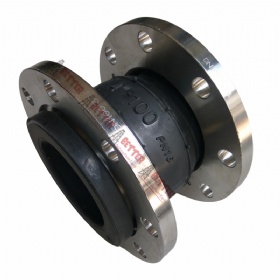
A rubber expansion joint is an arch-type flexible non-metallic connector fabricated from natural or synthetic rubber and fabrics, usually with metal reinforcements, to isolate vibration and noise and provide stress relief in piping systems caused by thermal changes, mechanical vibration and other system movements. Generally, it shall be designed & fabricated in accordance with ASTM F1123 and “Technical Handbook on Rubber Expansion Joints and Flexible Pipe Connectors”, or in accordance with special customer requirements. Besides, the Chinese standard HG/T 2289 Flexible Rubber Joints sometimes may apply.
Rubber expansion joints provide flexibility and concurrent
movements, isolation of vibration and noise, resistance to corrosion, abrasion
and erosion in various piping systems. They are widely used in process piping
systems, urban heating & air conditioning systems, water supply systems,
sewage treatment, food industry, ship building industry, power generation, as
well as pharmaceutical industry.
Construction Features
The 3-dimensional model of a spool arch type rubber expansion
joint. The sectional view of the inner tube, carcass and cover.
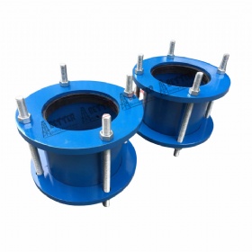
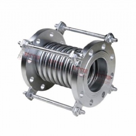
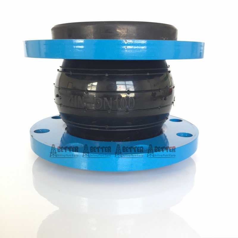
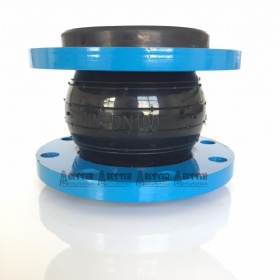
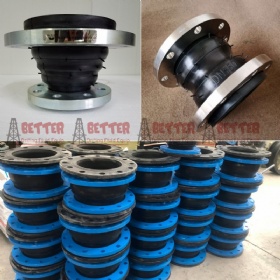
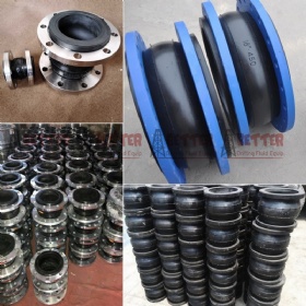
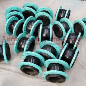
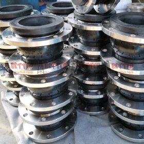
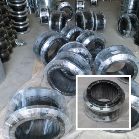
Miscellaneous design patterns of rubber expansion joints are available: (1) Integral Rubber Flanges – The end connection flanges of the joint are integrally formed as a part of the elastomeric bellows. It is also called “spool arch type rubber expansion joint”. (2) Floating Metallic Flanges – The metal flanges shall have a groove to accept the molded bead in the body at each end of the expansion joint bellows. (3) Spherical Type – Long radius arch, either single sphere or twin sphere, to provide better movement capability and strength. (4) Control Units – Tie rods or control rods are provided to minimize possible damage to the expansion joint caused by excessive motion of the piping system. (5) Custom Designs – rectangular flange connection, threaded union connection, tapered reducer type, no-arch U type, hinged type, gimbal type, sleeve type, PTFE lined type.
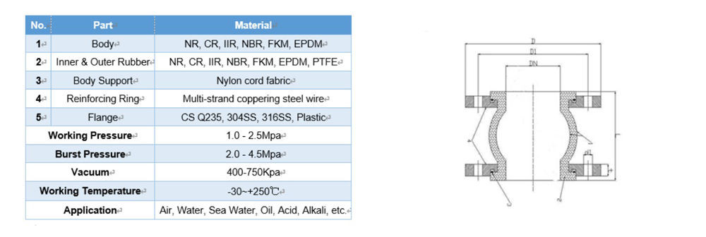
Diagrammatic Drawing & Technical Parameter
DN
Length
Axial Displacement mm
Horizontal
Displacement
mm
Angular
Deflection
(a1+a2)°
mm
inch
mm
Extension
Compression
32
1.25
95
6
9
9
15
40
1.5
95
6
10
9
15
50
2
105
7
10
10
15
65
2.5
115
7
13
11
15
80
3
135
8
15
12
15
100
4
150
10
19
13
15
125
5
165
12
19
13
15
150
6
180
12
20
14
15
200
8
210
16
25
22
15
250
10
230
16
25
22
15
300
12
245
16
25
22
15
350
14
255
16
25
22
15
400
16
255
16
25
22
15
450
18
255
16
25
22
15
500
20
255
16
25
22
15
600
24
260
16
25
22
15
700
28
260
16
25
22
15
800
32
260
16
25
22
15
900
36
260
16
25
22
15
1000
40
260
18
26
24
15
1200
48
260
18
26
24
15
1400
56
350
20
28
26
15
1600
64
350
25
35
30
10
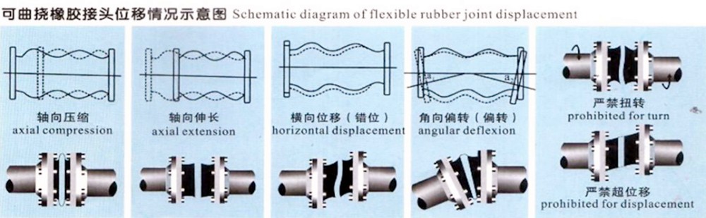
Working Principle
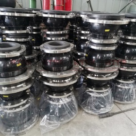
Production Process